Wall Footing - Results
The locations for output of wall footings are the Wall Footing Results browsers and the wall footing Detail Report.
- For more information on defining wall parameters, see Wall Footing Definitions.
- For more information on modeling requirements, see Wall Footings - Modeling.
- For more information on calculation details, see Wall Footings - Design.
Wall Footing Results Browser
To view the wall footing results browser, click Wall Footing Design from Results Browser drop-down in the Results tab on the ribbon, or select Wall Footing Design from the Results section in the Explorer panel. These output browsers are meant to summarize the results for wall footings. To see more detailed information, view the Detail Report by selecting Detailed Report in the Results tab on the ribbon.
Footing Code Checks

Click on image to enlarge it
The Wall Footing Code Check Spreadsheet gives the flexural and shear checks and capacities for both the footing toe and heel design. For more information on the design of these portions, see the Footing Design Considerations section of the Wall Footings - Design topic and the Detail Report section.
Wall Code Check (Concrete)

Click on image to enlarge it
The Wall Code Check (Concrete) Spreadsheet gives bending and shear code checks, as well as capacity values for the wall stem. To get a detailed sketch of this information, see the Detail Report.
Masonry Wall Results
Service
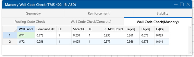
Click on image to enlarge it
Strength
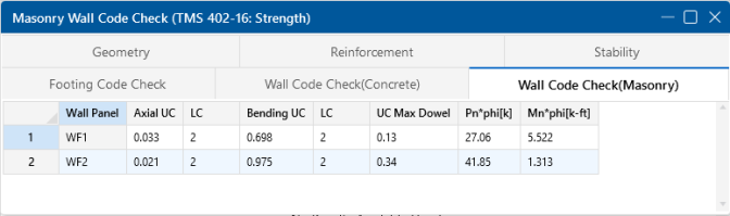
Click on image to enlarge it
The Wall Code Check (Masonry) Spreadsheet gives bending and shear code checks for the wall stem. To get a detailed sketch of this information, see the Detail Report.
Geometry

The Wall Footing Geometry Spreadsheet gives a summary of the overall geometry of the wall and footing. This is a reiteration of input parameters.
Reinforcement

Click on image to enlarge it
The (Reinforcement tab gives all of the steel requirements for the wall footing, including wall, footing and dowel reinforcement.
Stability

Click on image to enlarge it
The Wall Footing Stability Spreadsheet gives information for soil bearing, overturning and sliding checks for wall footings.
For the Soil Bearing Checks, the Bearing UC column is meant to act as the code check value. Anything exceeding 1.0 here means you are failing this check.
- The Allowable Bearing Pressure value is defined for each soil region in the model. If your wall footing lands on multiple soil regions, the smallest allowable bearing pressure will be used.
- If you fail the soil bearing checks we will not give a full solution to your model. We will, however, give you the soil pressure diagrams so you can decide how you want to reconcile this failure.
For more information on the specifics of the overturning and sliding checks, see the Footing Design Considerations section of the Wall Footings - Design topic, as well as the Detail Report.
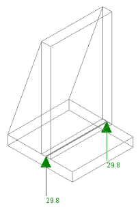
Graphic Results
The reactions for the wall footing can be viewed in the Model Display Options dialog. For wall footings, only the vertical reactions are given. The total vertical load is calculated and the display divides that value by two and places reactions at the ends of the walls.
Wall Footing Detail Report Information
The Retaining Wall Detail Report provides detailed information about geometry, materials, criteria, design and stability checks and sketches associated with the retaining wall. Here we will walk through each section of the report.
Header

Click on image to enlarge it
The header of the Detail Report is useful for navigating and viewing information in the wall footing reports.
- The LC drop-down allows you to view the overall loading diagram and the axial, shear and moment diagrams for the stem by individual load combination. Every other item in the Detail Report is enveloped, or results are given for each LC individually.
- The arrows allow you to click through Detail Reports for the different wall footings in the model.
- The Options button opens up the Detail Report Options dialog, shown below. This allows you to customize exactly what you see in the Detail Report.

Click on image to enlarge it
- The Print button opens the print dialog to print the report.
- The Add to Full Report check box will include the Detail Report in the available output when printing your overall project report.
Rebar Diagram

Click on image to enlarge it
The Rebar Diagram section gives a full sketch of wall footing dimensions, reinforcement size and spacing and cover dimensions.
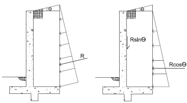
Loading Diagram

Click on image to enlarge it
The Loading Diagram section gives a visual of all the calculated pressures and loading on the wall. This loading information is what is used to provide the design checks for the wall footing. Loads shown on the top of the wall footing are any externally applied loads to the wall, divided out on a per foot basis. For more information on the calculation of these pressures, see the Footing Soil Pressure Considerations and Wall Pressure Considerations sections in the Wall Footings - Design topic.
- This diagram is based on the load combination shown in the dropdown at the top of the report.
- If your retaining wall has a sloped, a portion of the hydrostatic loads will be applied in the vertical direction of your wall. The cosine of these forces will be applied horizontally as a pressure. The sine of these forces will be applied as a vertical force that is shown along the inside face of the wall and conservatively applied at the top of the wall.
Input Data
Concrete Wall

Click on image to enlarge it
Masonry Wall
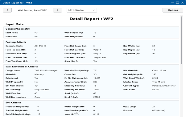
Click on image to enlarge it
The Input Data section provides input information from the Wall Footing Definitions and design information, such as the reinforcement spacing and K calculations (see Soil Considerations).
Wall Design
Concrete Wall

Click on image to enlarge it

Click on image to enlarge it
The Axial, Shear and Moment Diagrams are based on each load combination from the drop-down list.
The Axial/Bending Checks are given for both the interior and exterior faces of the wall. Note that only a propped cantilevered wall will have any bending in the "Gov Mu Ext", unless there is a large externally applied load in the direction opposite the soil loading. The code checks here are based on a concrete wall interaction diagram and bending capacity checks also consider compression reinforcement.
The Wall Reinfrocement section provides the minimum reinforcement requirements and the reinforcement provided for the wall.
The Shear Details provide both the concrete shear check (at a distance "d" from the base of the wall) and the dowel shear checks (at the base of the wall). Note that the dowel checks are only done for retaining walls with a footing that is not defined as monolithic with the wall. For more information, see Wall Footing Definitions - General.
The Enveloped Wall Forces section gives other forces found in the wall that the program did not explicitly use. For example, the wall footing will not be designed for in plane shears, but those forces will be reported here.
Masonry Wall (ASD)

Click on image to enlarge it
The Axial and Bending Details give the values used in the axial and flexural code checks at the location which controls the combined check (fa/Fa)+(fb/Fb).
For ASD design, the maximum bending stress in the flexural reinforcement is reported as fs, and the allowable steel bending stress as Fs. These values are given for the Load Combination and section that produce the maximum code check (fs/Fs).
The Shear Details give the maximum shear demand as fv. The allowable shear stresses are then reported as Fv.
Design Details
Radius of Gyration (r): The out of plane radius of gyration for the wall.
h/r: Slenderness ratio of the wall.
k: This value multiplied by d gives the depth to the neutral axis.
d: The depth between the extreme face of masonry in compression and the center of the tension reinf.
j: This value multiplied by d gives the moment arm between the compression and tension resultants.
Width for Shear: This is the value used to calculate the shear capacity. For fully-grouted walls, this is simply the center to center spacing of vertical reinforcement. For partially-grouted walls, this value is conservatively taken as the width of the grouted cell plus the thickness of the web and end wall on either side. An example of this can be seen in Example 6.3 (p6.65) of "Design of Reinforced Masonry Structures" by Taly, copyright 2001.
Corresponding M & P: These are the moments and axial forces used to calculate the shear capacity. These are both conservatively taken as the maximum M & P in the entire wall, rather than the M & P at the location of maximum shear.
M/(V*d): This is the M/Vd ratio used to calculate the shear capacity.
Masonry Wall (Strength)

Click on image to enlarge it
The Axial Detailsprovide the axial code check for pure compression forces. The Pn at max Mom value reported is the maximum allowable axial force based on either Section 9.3.5.4.2 or Equations 9-11 and 9-12.
The Bending Details are explained below:
- Mu/ phi*Mn represents the ratio of applied moment to moment capacity of the wall.
- Mu, max is the out-of-plane bending moment at the controlling location of the wall.
- phi Mn is the out-of-plane moment capacity of the wall at the controlling location. It is calculated per Section 9.3.5.2.
- phi is the strength reduction factor specified in Section 9.1.4.
- Location is the elevation of the wall which resulted in the highest (Mu / phi*Mn) or Pu/Pn ratio. It is the location at which Mu and Pu are used to calculate phi Mn.
- Load Combination is the load combination which resulted in an Mu and Pu which yielded the highest (Mu / phi*Mn) ratio.
For more information on a T-section analysis, see Wall Footings - Design.
The Sectional Properties provides design values based on the center to center spacing of reinforcement and are explained below:
The center to center distance between reinforcing Total Width and the Eff Width (which accounts for partially grouted walls) are both reported in this section. The Flange Thick tf refers to the thickness of the face shell, whereas the Effective Thick te refers to the overall effective depth of the block.
The gross area and moment of inertia are reported along with the modulus of rupture, cracking moment, neutral axis, modular ratio between steel and masonry, and the cracked moment of inertia.
The area of steel As and the effective area of steel Ase are reported, with the effective area based upon As + Pu/fy.
The gross steel ratio (rho gross) is calculated as the area of steel divided by the total area of the section.
The Rho Provided (%) is calculated as the area of steel divided by the total width times the effective depth (As/bd). This is limited to a Rho Maximum (%) value of 0.5 * rho balanced per the UBC-97 Section 2108.2.3.7. This provision was implemented in future codes as well.
The Sectional Properties gives a number of the properties used during the iterative slender wall design procedure. All of these properties are reported based on a section of wall equal to the center to center spacing of the reinforcement.
Footing Design

Click on image to enlarge it
This section provides an enveloped report of the footing design for both the top and bottom bars. The top of this section provides the flexural and temperature & shrinkage minimums. For the toe and heel, we provide shear and moment checks for the worst case load combination. For more information on footing design considerations, see Wall Footings - Design.
- If the bottom bar is in tension in any solved combination for both the toe and the heel, the program will envelope the worst case reinforcement for both the toe and the heel.
- If the minimum spacing requirements defined in the Retaining Wall Definition do not meet minimum code requirements, you will receive a warning message in the Detail Report.
Overturning Check (Service)

Click on image to enlarge it
This section gives overturning results for all service load combinations that are solved. The SF Min/SF column is meant to act as the code check value. Anything exceeding 1.0 here means you are failing this check. See the Serviceability Considerations section of the Wall Footings - Design topic for more information.
Sliding Check (Service)

Click on image to enlarge it
This section gives sliding results for all service load combinations that are solved. The SF Min/SF column is meant to act as the code check value. Anything exceeding 1.0 here means you are failing this check. For more information, see the Serviceability Considerations section in Wall Footings - Design.
Soil Bearing Check (Service)

Click on image to enlarge it
This section gives soil bearing check results for all service load combinations that are solved. The Bearing UC column is meant to act as the code check value. Anything exceeding 1.0 here means you are failing this check.
- The Bearing Allowed column is the allowable bearing pressure. This value is defined for each soil region in the model.
- If your wall footing lands on multiple soil regions, the smallest allowable bearing pressure will be used.
- If you fail the soil bearing checks, we will not give a full solution to your model. We will, however, give you the soil pressure diagrams so you can decide how you want to reconcile this failure.